 PONKA
Cyclone and baghouse collection
Separate a coarse fraction before fabric filtration when the dust stream and operating duty justify two collection stages.
ExploreDust collection / PFD-29
Capture dust at crushing, screening and transfer points, then separate it from the extracted air using fabric filtration.
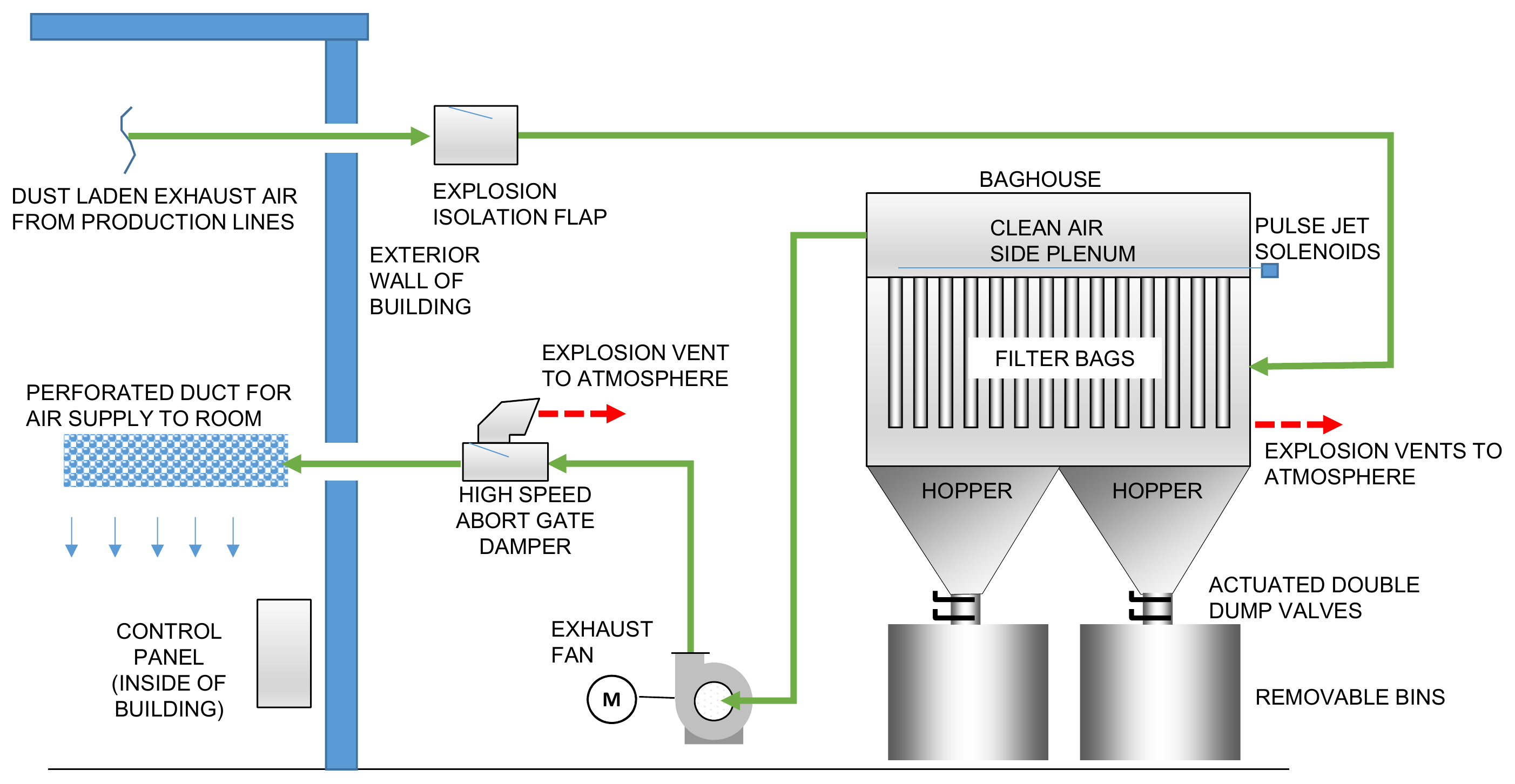
Dusty air from the production lines passes through an isolation flap and enters the baghouse. The bags retain dust; cleaning pulses release it into two hoppers, and double-dump valves empty the hoppers into removable bins. The fan draws filtered air from the upper chamber. This drawing shows the air returning to the room through an abort gate and perforated duct; whether room return is appropriate needs a separate assessment.
Mining applications
A baghouse connects local capture points to a central dry collection system. It is a candidate where the mineral dust, moisture and operating temperature suit fabric filters and where collected fines can be handled in a contained discharge.
Hoods and enclosures draw dusty air away from the process opening and into a balanced duct network.
Air passes through filter bags while collected dust builds on the filter surface. The cleaning arrangement releases accumulated dust into the hopper.
Discharge valves transfer the dust into enclosed bins or downstream handling equipment without leaving the hopper open to the room.
The fan moves air through the system to a discharge arrangement selected for the contaminants and site. Room-air return requires a separate engineering assessment.
| Component | Role in the system |
|---|---|
| Capture hoods and ductwork | Collect and transport dust from each process opening. |
| Baghouse and cleaning system | Separate dust using fabric filters and controlled cleaning cycles. |
| Hopper and discharge valves | Contain collected fines during removal. |
| Exhaust fan ↗ | Provide the airflow and pressure required by the complete system. |
Linked components open the VentilationComponents.com supplier catalogue. Equipment selection forms part of the system engineering.
Before equipment selection
Tell us about the material, operating conditions and problem you need to address.