 PONKA
Steam-heated make-up air
Filtered, heated outdoor air to replace air removed by process exhaust and dust collection.
ExploreVentilation & HVAC / PFD-04
Temperature control and filtered pressurization for electrical and control equipment rooms.
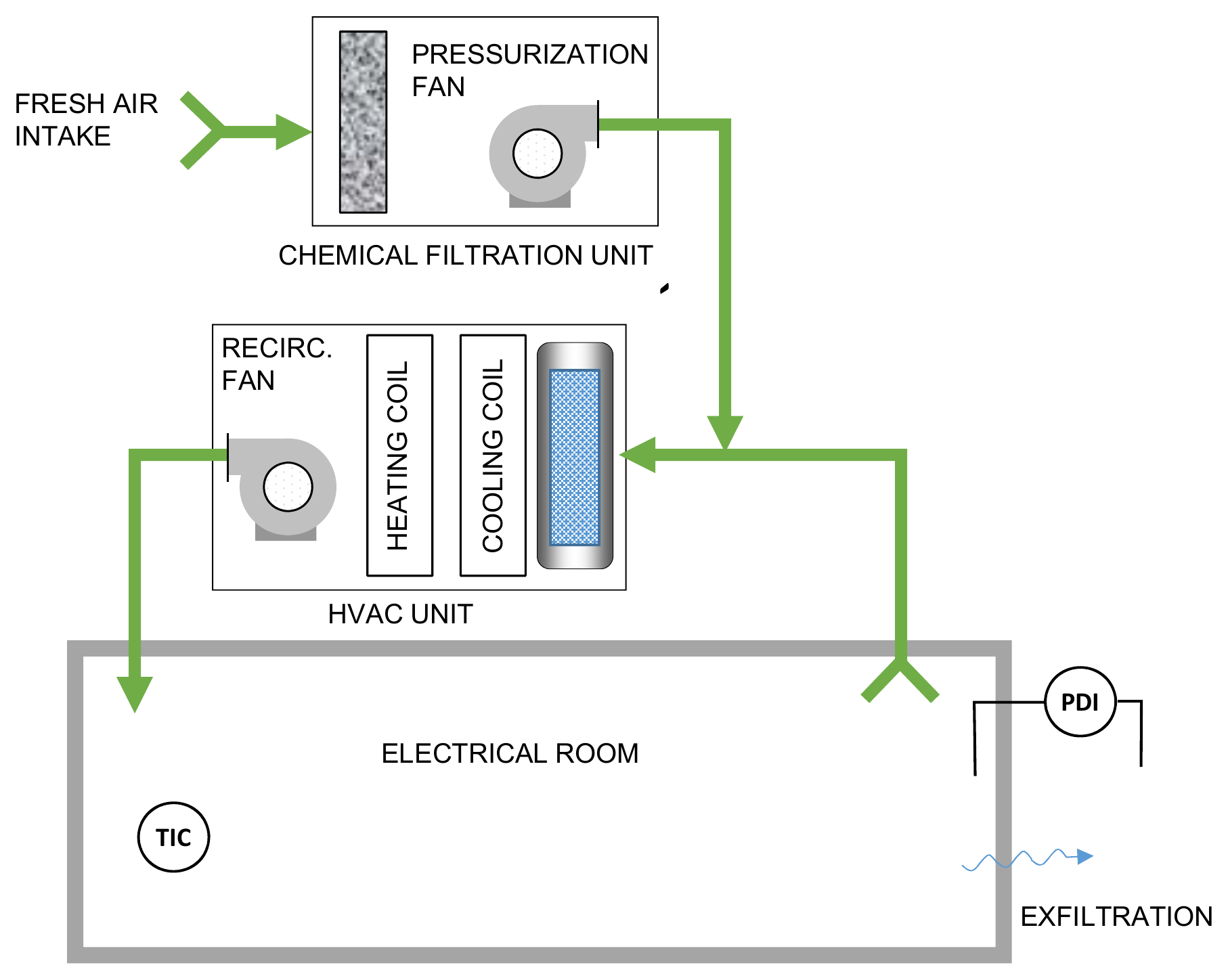
Outdoor air enters the chemical filtration unit at the top. Its pressurization fan feeds the treated air into the electrical room's return duct, upstream of the HVAC filter and coils. The recirculation fan sends the conditioned air back to the room. The instruments show room temperature and the pressure difference across the room boundary.
Mining applications
Electrical rooms bring together equipment heat loads and exposure to the surrounding plant environment. This arrangement combines room cooling and heating with a separate filtered supply. Chemical filtration can be considered where identified gaseous contaminants call for suitable media, alongside particulate filtration.
The intake location and filtration stages are selected for the particulate and gaseous contaminants present.
A dedicated pressurization fan introduces air through the selected treatment section.
A room-conditioning loop circulates air through filters and heating or cooling coils to address the electrical equipment load.
Temperature and differential-pressure instruments provide operating feedback for the room and supply arrangement.
| Component | Role in the system |
|---|---|
| Filtration unit ↗ | Houses selected particulate filters and, where needed, gas-specific chemical media. |
| Pressurization fan ↗ | Supplies filtered air to the room. |
| HVAC unit | Conditions the room air to address equipment and seasonal loads. |
| Room instruments | Indicate temperature and pressure relative to the adjoining area. |
Linked components open the VentilationComponents.com supplier catalogue. Equipment selection forms part of the system engineering.
Before equipment selection
Tell us about the material, operating conditions and problem you need to address.