 PONKA
Steam-heated make-up air
Filtered, heated outdoor air to replace air removed by process exhaust and dust collection.
ExploreVentilation & HVAC / PFD-03
A dedicated filtered supply fan supports a defined room-pressure relationship alongside heating and cooling.
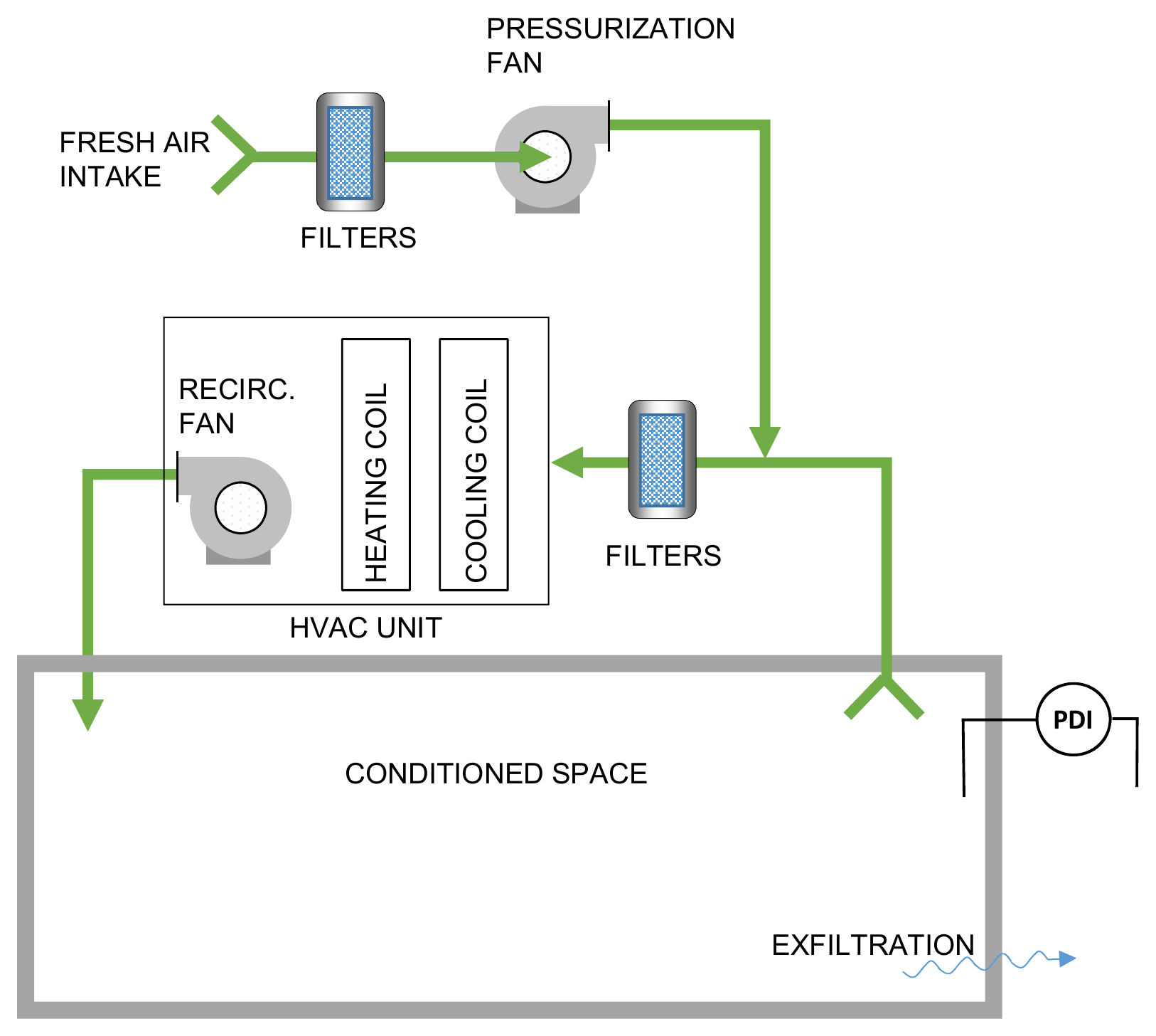
At the top, outdoor air passes through a filter and a dedicated pressurization fan. It joins air returning from the room just before the second filter and the HVAC unit. The heating and cooling coils condition this combined air, and the recirculation fan delivers it to the room. The outward arrow shows leakage, while the pressure indicator compares the room with the adjoining space.
Mining applications
A room beside a dusty processing area needs an intentional boundary between indoor and surrounding air. A separate pressurization fan supplies filtered air while an HVAC unit manages room temperature. The target pressure and filtration depend on the contaminants, room envelope, and operating conditions.
The dedicated intake draws air from a selected location and passes it through a filtration stage.
The pressurization fan supplies air to offset leakage and help maintain the specified room pressure.
The HVAC loop filters and heats or cools room air where recirculation is suitable for the room conditions.
Differential-pressure indication helps identify changes associated with doors, leakage, filter loading, or fan operation.
| Component | Role in the system |
|---|---|
| Intake filtration ↗ | Captures incoming particulate according to the selected filter specification. |
| Pressurization fan ↗ | Provides a dedicated supply to the room air balance. |
| HVAC unit | Manages the room heating and cooling load. |
| Pressure indication | Shows room pressure relative to the selected reference area. |
Linked components open the VentilationComponents.com supplier catalogue. Equipment selection forms part of the system engineering.
Before equipment selection
Tell us about the material, operating conditions and problem you need to address.